Have you ever run into this when you adapt an existing design in SOLIDWORKS?
- You change a shape or dimension slightly, and the whole model falls apart.
- You change a shape or dimension slightly, and it turns into an unintended shape.
- You change a shape or dimension slightly, and errors appear everywhere.
In fact, the cause of many of these problems is sketch constraints.
The sketch is the foundation of a 3D shape.
If your understanding of sketches is vague, you end up with a “fragile model” that cannot handle design changes, no matter how carefully you model.
If you build up features without understanding sketch constraints, even a small dimension change can make the entire model fall apart.
When that happens, you spend a lot of time and effort fixing the model.
I believe the cause of fragile models is a missing perspective: “communicating your design intent to SOLIDWORKS.”
This is hard to pick up just by learning the operations in a tutorial.
I’m a mechanical engineer who uses SOLIDWORKS every day and holds the Certified SOLIDWORKS Professional (CSWP) certification. In this article, I explain “the basics of sketch constraints” that even beginners can put into practice right away, and “the one idea that reduces design mistakes.”
By reading this article, you will gain more than just operating skills: a way of thinking that helps you build models that are resilient to design changes and easy to reuse.
Once you can build a “robust model” that doesn’t break easily, you can dramatically cut the time and effort you spend on dimension and shape changes.
If your dimension changes never seem to go smoothly, this article is for you.
Let’s level up as designers together. It starts with how you build a single sketch.
What Are Sketch Constraints? Basics for Beginners
In SOLIDWORKS, sketch constraints are rules that fix the position, shape, and relationships of sketch entities (lines, circles, points, and so on).
In SOLIDWORKS, geometric constraints are called relations and dimensional constraints are simply dimensions. This article uses “constraints” for both.
Understanding Constraint Status
You can tell whether a sketch entity is completely fixed by the color of its line.
- Fully Defined: All degrees of freedom are constrained and the entity cannot move. It is displayed in black.
- Under Defined: Degrees of freedom remain, so the entity may move unexpectedly when you drag it with the mouse. It is displayed in blue.
In a sketch, aim to make every line and point you draw Fully Defined.
If Under Defined entities remain, the sketch may look fixed at first glance, but when you later change a dimension or add another feature, the shape can change in unexpected directions and lead to design mistakes.
Judge whether a sketch is finished by checking that all of the sketch entities are black, not by how the shape looks.
You can also spot an Under Defined sketch in the FeatureManager design tree. If Under Defined sketch entities remain, a (-) mark appears before the sketch name.
The Two Types of Constraints and Their Roles
To fully define a sketch, you add constraints to the sketch entities.
Constraints fall into the following two broad types.
| Dimensional constraints (Dimensions) | Determine size | Specify length, angle, diameter, and so on as numerical values |
| Geometric constraints (Relations) | Determine relationships between entities | Specify Parallel, Perpendicular, Tangent, Concentric, Symmetric, and so on |
Many beginners tend to reach for dimensional constraints, which are easy to see.
However, experienced designers use geometric constraints heavily.
The reason ties into the one idea I describe in the next section.
The One Constraint Mindset Experienced Designers Use
What experienced designers always have in mind when they constrain a sketch is to express the “design intent” with constraints.
This is not a box-ticking goal like “make the sketch black.”
What matters is telling SOLIDWORKS exactly the intent the designer has built in: “this part should always sit in this position relative to that part.”
And to convey the design intent accurately, there are many situations where choosing a geometric constraint rather than a dimensional constraint is the better option.
Why Choose Geometric Constraints
Geometric constraints are a good choice when “you want to keep a relationship even if the dimensions change.”
For example, suppose your design intent is “the two holes always have the same diameter and sit symmetrically about the centerline.”
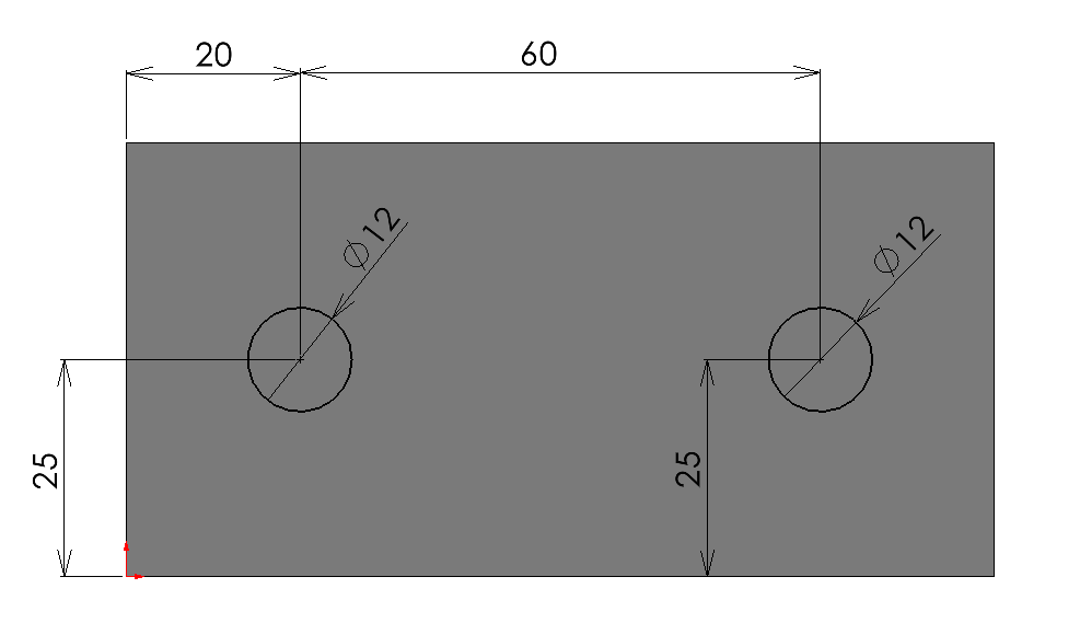
Every time you change the diameter of one hole, you have to change the diameter of the other hole by hand as well.
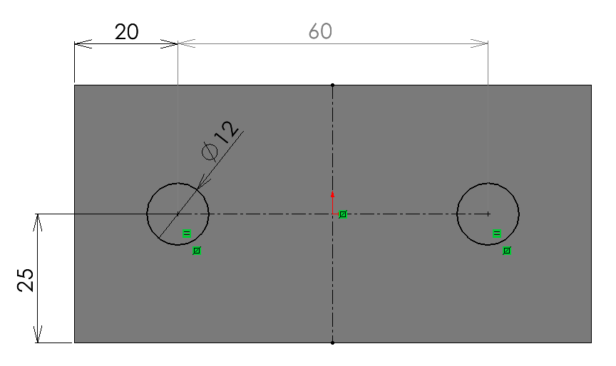
Just change the diameter of one hole, and the other hole is updated automatically.
With geometric constraints, you can reduce the number of places where you have to enter dimensions. In the plate above, one diameter dimension is enough instead of two.
Dimension changes happen frequently during design.
A model that has to be corrected by hand every time is very likely to cause design mistakes when you miss an update.
Geometric constraints let you lock in the fundamental relationships of the model.
That removes the need to type dimensions by hand and gives you a “robust model” that stands up to design changes.
Step by Step: Reaching “Fully Defined” as Quickly as Possible
To build a robust model, follow the steps below and aim to make the sketch Fully Defined (black).
Decide the sketch’s anchor (fixed point)
Fix (constrain) the reference point of the sketch to the origin or to an edge of another feature.
Define relationships with geometric constraints
Apply geometric constraints such as Parallel, Perpendicular, Symmetric, and Tangent first, to define the relationships between entities.
Set the size with dimensional constraints
Use dimensional constraints to fill in the remaining degrees of freedom and turn the whole sketch black (Fully Defined).
Sketch complete
By drawing your sketches this way, your work becomes more efficient, and you end up with a sketch that clearly reflects your design intent.
3 Constraint Techniques That Prevent Design Mistakes
Here are three concrete constraint techniques that experienced designers actually use to prevent design mistakes before they happen.
Technique 1: Use Symmetric Constraints and Midpoints
Define symmetric shapes with a Symmetric constraint.
With a Symmetric constraint about a centerline, changing a dimension on one side automatically updates the shape on the other side.
Also, when you want to place something at the center, use a Midpoint constraint.
It is handy because whatever you place stays centered even when the dimensions change.
Symmetric constraints and Midpoint constraints are very useful techniques when you model symmetric shapes.
They halve the number of places you need to fix when the design changes, which helps prevent design mistakes caused by missed corrections.
It isn’t a sketch technique, but when you extrude, using Mid Plane also gives you symmetry in the 3D shape. Please give it a try.
Technique 2: Use Centerlines and Points
Insert centerlines (construction geometry) and points, which don’t affect the actual shape, into the sketch and base your constraints on them.
For example, when you define the center position of a hole, don’t dimension the hole itself. Instead, dimension from a centerline and put the hole’s center point on that centerline.
This not only makes the hole position easy to change, but also makes the design reference clear and makes your intent easier for other designers to understand.
Placing holes along a centerline is easy to see at a glance, so I use it a lot myself.
If you turn on Automatic relations in System Options, simply drawing a horizontal or vertical centerline adds the matching constraint automatically.
Also, if you add an Equal constraint to centerlines, you can easily place items at equal intervals.
Technique 3: Constrain with External References in Mind
Sketching with the assembly in mind can also prevent design mistakes in a single part.
- Single-part constraints: constraints that stay inside the sketch.
- External references: constraints that reference something outside the part (a feature of another part or of the assembly).
By defining intent such as “this part’s hole always aligns with the pin of another part in the assembly” through an external reference, you can prevent design mistakes such as interference and misalignment when the assembly is put together.
However, be careful: heavy use of external references can make files heavier to work with and errors more likely.
External references are a double-edged sword.
They are useful when used well, but they have downsides, so making everything an external reference isn’t a good idea.
Summary
In this article, I explained the basics of sketch constraints and “the one idea that reduces design mistakes.”
The key tips for sketches that prevent design mistakes are as follows.
- Always make the sketch Fully Defined (black)
- Prioritize geometric constraints, and set the size with dimensional constraints last
- Constrain the sketch so that your design intent comes across
If you can put your design intent into the sketch accurately, you can build a robust model that is less prone to errors and mistakes.
Please keep this in mind the next time you sketch.
However, the constraint techniques in this article don’t apply to every case, so please use them case by case.
What matters is thinking about “how can I put my design intent into the sketch accurately?”
Rather than following this article to the letter, I hope you’ll take it as a way of thinking you can apply when you design.
Thank you for reading to the end.