Every time you create a new file in SOLIDWORKS, do you find yourself repeating the same settings changes?
If you change the units every time, or fix the drawing border every time, that is a big loss of time.
If you want to work efficiently in SOLIDWORKS, I strongly recommend setting up your own document template.
The default templates are designed to be general-purpose. For production work, they often lack something you need, or do not match your company’s standards.
Customizing them gives you these benefits.
- Less time spent: You no longer have to change the same settings each time.
- Fewer mistakes: You avoid errors such as the wrong unit system or the wrong drafting standard.
- Consistent quality: A whole team or company can share the same drawing appearance and properties.
This article explains how to create and use a SOLIDWORKS document template, and which settings I recommend putting in it, from the viewpoint of everyday work.
Customizing your templates is an easy way to improve your efficiency.
What Is a SOLIDWORKS Template?
SOLIDWORKS has several kinds of templates.
This article focuses on the document template.

The document template is the main one.
There are other kinds of templates too, such as the bill of materials template.
- Document Properties: mainly the drafting standard, the unit system, and the dimension style
- File properties: the items you want to store as information about the model
- Display state of the 3D model: the background brightness, the display style, the items shown in the FeatureManager design tree, and so on
- Drawing border and line styles for drawings
If you set up your document template well, you can unify the look of your models and drawings the way you or your company like.
It also makes your work more efficient, both in design and in the steps after design.
For example, a common drafting standard, unit system, and drawing border are essential when you handle drawings. A common font, line style, and arrow size also change how easy a drawing is to read.
Whether the background is light or dark also affects how tired your eyes get while you model.
You need to set up a document template separately for each of the three file types: part, assembly, and drawing.
In addition, if you need four drawing sizes, for example A1, A2, A3, and A4, you need to create four drawing templates.
So you need two model templates and four drawing templates (for A1 to A4).
It is not difficult, but it takes a little effort to make them.
Document Properties vs. System Options
SOLIDWORKS has another kind of setting: System Options.
Let’s get a rough idea of how Document Properties and System Options differ.
- System Options
These apply to all files, both existing and new. They are stored in the registry, not in the file. You can think of them as settings for each user, each device, or each PC. - Document Properties
These are stored in the file. Even on a PC with different settings, the file is used and displayed under the same conditions. The unit system or the dimension display style does not change because of a PC’s settings.
Because a template stores Document Properties, the settings you build into it travel with every file you create from it.
How to Save and Use a Document Template
Let’s look at how to make a document template.
You do not start from zero. You customize one of the default SOLIDWORKS templates for your own use.
The steps below use a part template as an example.
Save a Template
- Click New and create a new part from any existing part template (the default one is fine).
- Set the items you want in Document Properties. If there are other settings you want, such as file properties or the display state, set those too.
- As an example, let’s change the drafting standard. Click Tools > Options and open the Document Properties tab.
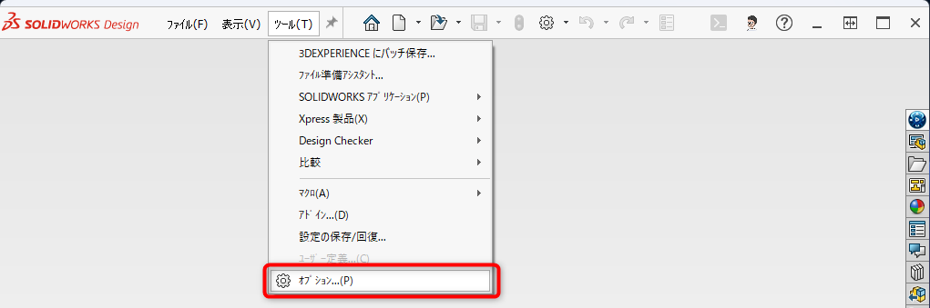
- Go to Drafting and change Overall drafting standard to the one you use (for example, ISO, ANSI, DIN, or JIS). Then click OK to close the window.
- Click File > Save As. Set Save as type to Part Templates (*.prtdot).
- Browse to a folder of your own (create one first if you need to), and save the file there.
Give the folder a name that tells you at a glance what kind of templates are inside. I explain why in the next section.
In this example, I saved a document template file named Sugitama_Parts.prtdot in a folder named sugitama_template.
Assembly templates use Assembly Templates (*.asmdot) and drawing templates use Drawing Templates (*.drwdot) as the file type. SOLIDWORKS may suggest its default template folder when you choose a template type. It is safer to keep your own templates in a folder outside the SOLIDWORKS installation folder, so that an upgrade or reinstall cannot overwrite them.
Use the Template
After you save a template, make it available in SOLIDWORKS. To use a template you created, you need to change a System Option.
- Click Tools > Options to open the System Options.
- On the System Options tab, select File Locations.
- Make sure Show folders for is set to Document Templates, and click Add.
- In the folder window that opens, select the folder that holds your templates and click Select Folder.
- Check that the folder you selected is now in the list, and click OK.
- Click File > New. If the dialog is not already in the Advanced view, switch to Advanced.
A new tab named sugitama_template appears, and the template Sugitama_Parts is now available.
The name of the folder becomes the name of the tab. That is why I suggest giving the folder a name you can recognize at a glance. Make sure the folder contains at least one template file, or the tab may not appear.
Recommended Settings for Your Template
Here are the settings that I think are useful to build into a template.
Settings for Parts and Assemblies
First, the settings for part templates and assembly templates.
These settings cover the information the model itself keeps, and the settings that make modeling easier.
1. Document Properties
Check the following items in Document Properties.
- Drafting standard: Choose the standard that your company and your customers use, such as ISO, ANSI, DIN, or JIS.
- Units: Millimeters, kilograms, and seconds are a practical choice if you work in metric. (To combine millimeters with kilograms, choose Custom on the Units page.)
- Font: Choose whichever font you like, but pick one that is installed on Windows by default. If you send the data to a customer who does not have your font, it will not display correctly.
- Image Quality: This controls how smooth curves look. A finer setting lowers performance, so be careful.
Some companies specify the arrow type, the font, and the size.
In that case, set these to match your internal standard.
2. Add Reference Axes
If you insert reference axes in the template (Insert > Reference Geometry > Axis), modeling and drawing become more efficient.
With axes in place, you can dimension from an axis or add relations to it while you model, which makes modeling easier.
You can also show the axes on the drawing, so you do not need to insert a centerline each time.
This is not a required setting, but it is a good one to add because it saves work.
After you create the axes, turn on the axis display (View > Hide/Show > Axes).
If you forget, the axes you made stay hidden.
3. File Properties (Custom Properties)
In SOLIDWORKS, you can register file properties (File > Properties) for both model files and drawing files.
The information you enter in the model’s properties can be read into the title block of the drawing automatically, and it can also be used to create a bill of materials automatically.
In SOLIDWORKS, the model and the drawing are linked, and the model is the parent. (The drawing is created by referring to the model.)
If you put the information in the model, it carries over to the drawing automatically.
Pick the items you want to register as properties, and set them up in the template.
Typical basic management items include the drawing number, model name, designer, drafter, and creation date. It also helps to add the items needed for manufacturing, such as material, heat treatment, surface treatment, and quantity.
If you need other items for management, add them as needed.
Filling these in makes drawing creation smoother.
Set up the model file’s properties so that you can use them in drawings.
The properties of a drawing file usually have no particular use, so you do not need to set them in the template.
4. View Settings
You look at the screen for a long time while you design. Set up the display so that it is as easy on your eyes as possible.
This is purely a matter of taste. I use the following settings.
- Display style: Shaded With Edges
- Background: I leave it at the default
- Floor reflection and floor shadow: turned off
Nothing unusual. My display is close to the default.
5. FeatureManager Design Tree Display
A cluttered FeatureManager design tree is hard to read, so tidy up how it is displayed.
If each part also shows its configuration and display state, the tree gets cluttered.
If a part has only one configuration, hide those names and the tree becomes clean and easy to read.
Settings for Drawings
1. Drawing Border (Sheet Format)
Set up the drawing border that you use on your drawings.
The border and the title block together are called the sheet format. You need one for each drawing size you use. Use the paper sizes your company uses, for example A1 to A4 in ISO, or A to E in ANSI.
To edit the border, right-click inside it and select Edit Sheet Format.
2. Line Styles
The basic line styles are available by default. If you want to use a special line style all the time, it is a good idea to set it up in the template.
For example, I often use these two:
- A line style that does not print, for design notes that I want to write on the drawing but not print
- A color-coded line style that makes revised areas stand out
Summary
This article explained how to set up and use a document template, and the settings I recommend building into it.
As you work with your template, you will find more and more things you want to add.
Do not try to do everything at once. Update the template as you go, and you will build one that is easy to use.
You can also create templates for specific situations, such as one for sheet metal parts, one for machined parts, and one for large assemblies.
I hope a template tailored to your work makes SOLIDWORKS more comfortable to use.
Thank you for reading to the end.